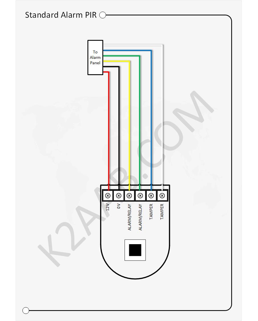
I have a standard alarm system in my home using a selection on reed switches and PIRs. These are all wired back to a control panel via 6 core cable; 3 pairs, power, tamper and trigger. I also have a Fibaro HC2 delivering home automation and secondary alarm functions.
Adding a Fibaro Universal Sensor to an existing PIR adds Z-Wave functionality that can then be used for scene triggers and alarm functions. In addition a temperature sensor can be added to give a room temperature reading.
I’ve always love getting my electronic kit out but just don’t seem to get the time any more. It’s so bad that when I got my breadboard out to build this project out it still had my university project still on it! First job strip the board 😦
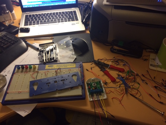
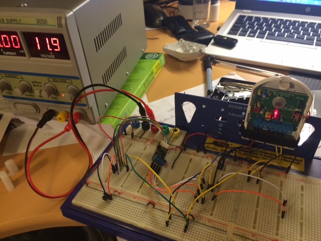
So once striped I connected up the board as per the circuit diagram below:
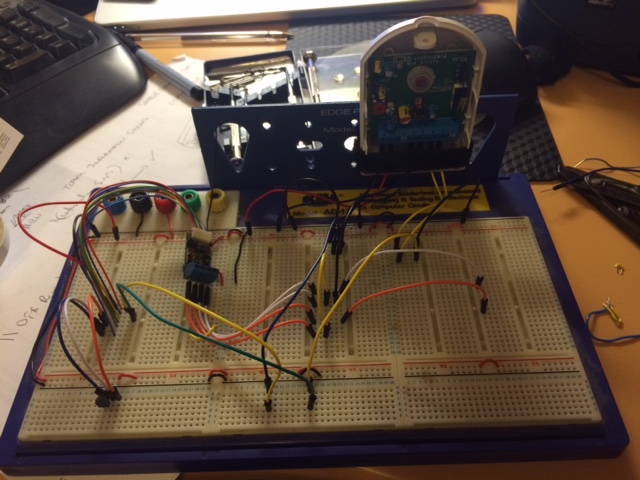
Adding the power and it all seems to work as required, triggering the alarm on motion and tamper:
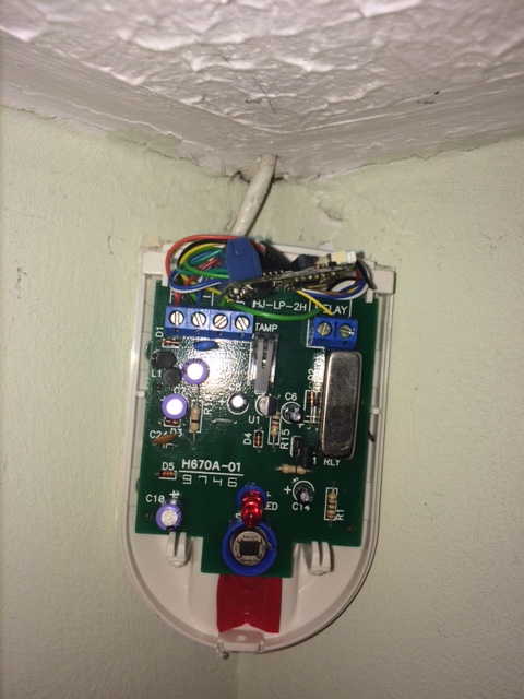
The next phase is to install the universal sensor into an existing PIR as I’d used a spare for testing:
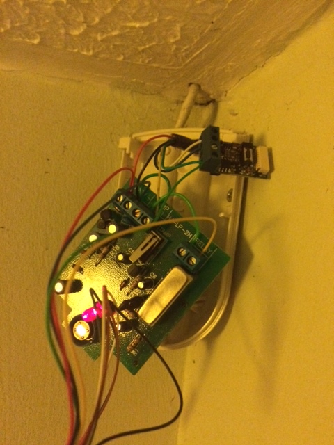
At this stage I also poked the temperature sensor out of the bottom of the PIR. It’s not the best position for a room temperature sensor but it gives a guide. The Universal Sensor tucks quite neatly out of the way at the top of the PIR:
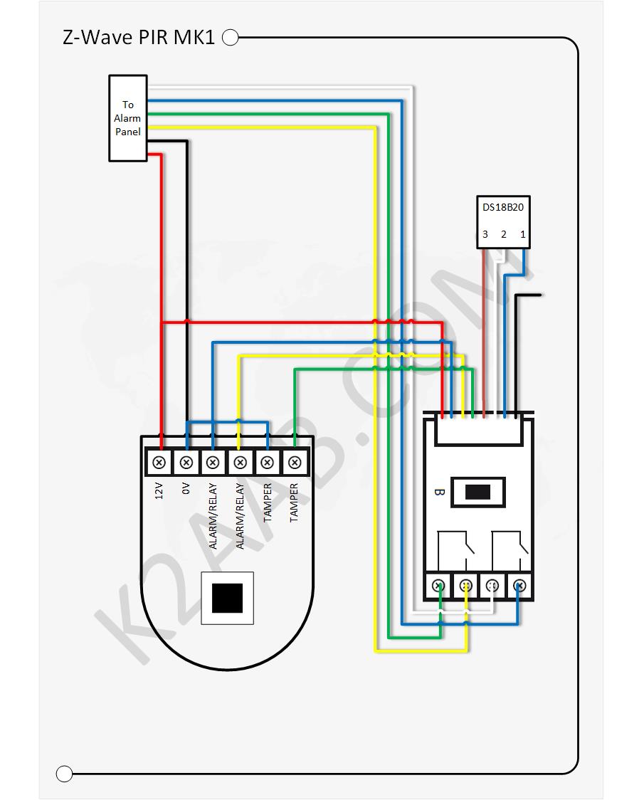
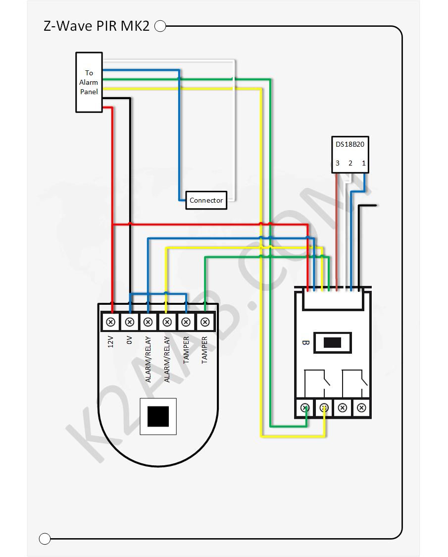
Full testing at this stage with the existing alarm failed as there was a tamper fault. There were two ways to fix this; firstly reconnect the tamper circuit direct to the PIR and not use half of the Universal Sensor, or bypass the tamper circuit in the PIR for the main alarm. The following diagram shows the latter and the option I went for. This way the Fibaro alarm is triggered by movement and by the PIR being tampered with, i.e. the cover opened. The main alarms tamper alarm is still triggered if the cable is cut/broken.

Hi,
I stumbled across your post whilst Googling around for wiring diagrams of Fibaro Universal Sensor and PIR sensors. I’m looking to make some of my PIRs `smarter` by being able to track motion activity and temperate in these rooms.
I’m no electrician so excuse the questions. My alarm PIR sensor has the following wires going to the labelled connectors on the PIR :-
Red – 12v
Black – 0v
Yellow – ALARM
Blue – ALARM
There are two extra inputs on the PIR for TAMPER which aren’t wired.
Am I correct in thinking I should wire up the Fibaro like so :-
Red (12v) – PIR 12v – Fibaro P
Black (ov) – Leave this wired to 0v
Link PIR Blue (ALARM) – Fibaro GND
Link Yellow (ALARM) – Fibaro INPUT 1
And then OUTPUT 1 to connected to the original Blue and Yellow wires back to the alarm panel.
What’s the reason for jumping the PIR blue to Fibaro Gnd?
The temperature sensor just hooks right up to Fibaro via its 3 wires?
Can this not be wired in the alarm so i could get the benefit of 2 PIRs?
LikeLike
Hi
Thanks for reading. I guess you have a few options.
If your main alarm panel does not have a tamper circuit then yes; connect the Universal Sensor to the 12v supply and ground as well as the leaving the PIR connected as it will still needs power too. Remove your current yellow and blue and connect these to the Fibaro output 1 connectors. Then connect the Yellow Fibaro lead to one of the Alarm connections on the PIR, the other connection for the alarm on the PIR also needs to be connected to ground.
At this point, your main alarm will operate as it always has but you’ll also have a z-wave motion sensor.
With the temp sensor, yes, just connect up the 3 wires to the 3 terminals on the BS18B20 in the correct order.
Now; as your PIR does have tamper connections you could also add z-wave tamer sensor by connecting the green to tamper and the other connection to ground. If someone opened the PIR you’d get a trigger, the output 2 does not need to be connected to anything for this.
Interesting thought on putting the Universal Sensor in the alarm panel and using for two PIRs. I don’t see why not, you’d need to test and make sure it worked, and that voltage drops were not a problem over the length of the cable. You’d also loose the ability of temperature monitoring in the room, unless you ran a 3 core cable to the room, Fibaro recommend this should not be more than 30 meters.
Hope that helps
Andrew
LikeLike
I more experimenting with this at the moment, I guess the question is a trade off between losing temperature readings over gaining the use of two PIR’s which ultimately will cost less as i’d only need 2 Fibaro’s where mounting them individually in PIRs will mean I need at a cost of £30 each from Vesternet.
So with the PIRs have 2 Tamper inputs this would suggest the alarm unit has a tamper circuit? The alarm is a Accenta G3. Looking at page 5 of (https://www.tlc-direct.co.uk/Technical/DataSheets/Ade/4pi175_A-G3_inst.pdf) would suggest there is a circuit but whomever wired mine up decided not to wire the tamper up. I’ve not checked other PIR’s.
Are you using this device through Samsung Smartthings by any chance?
LikeLike
Yes, I guess that’s what the trade off is.
Alarm tamper circuits are generally just a loop of wire that connects all your devices in series, any break in the circuit just triggers the alarm, if someone cut the wire or opened a PIR. The two connectors in the PIR are generally the two sides of a mechanical switch that when the PIR is closed the switch is closed too, open the PIR, the switch opens and the tamper circuit is broken. You may well see a switch in the middle of the circuit board that is pressed down when the cover of the PIR is fitted.
For my Z-wave controller I’ve got a Fibaro HC2.
Looking at your alarm, I’d say you do have a tamper circuit, you may find that the tamper terminals in the main board just have a jumper between them. Sounds like someone may have been trying to save, I’m guessing you only have 4 core cable and not 6 going to all your devices?
Regards
Andrew
LikeLike
Mat I see it has been a year since your post, however i was wondering if you managed to wire the Fibaro Universal Sensor into the Accenta G3 alarm box, as i have this box and would like to do the same?
LikeLike
what parameters did you use with the fibaro system to get this to poll correctly.
LikeLike
Hi Alex
These are the parameters I have set:
Polling time interval = Device uses global polling queue
Parameter 1 = 1
Parameter 2 = 0
Parameter 3 = 1
Parameter 4 = 1
Parameter 5 = 255
Parameter 6 = 255
Parameter 7 = 255
Parameter 8 = 255
Parameter 9 = 0
Parameter 10 = 20
Parameter 11 = 200
Parameter 12 = 0.5
Parameter 13 = 0
Parameter 14 = 0
Hope that helps
Andrew
LikeLike